The information in this brochure should be checked in detail by the professional engineer responsible for the project design to verify its accuracy; also, the assumptions and methods used to obtain the information should be reviewed to make certain they are applicable and suitable for the design.
Tables adapted from AISI Handbook of Steel Drainage and Construction Products.
Corrugated Steel Pipe - Arch Design Table
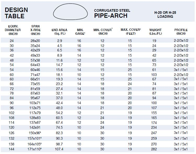
1. Minimum cover is measured from top of pipe to top of subgrade or top of rigid pavement. Minimum cover for heavy construction equipment or other excessive loading is 48 inches. H-20 or H-25 live loads are assumed in all cases.
2. Maximum height of cover is based on 2-ton/square foot corner soil bearing pressure. Heights of cover can be increased up to 100% with proportional increase in corner soil bearing pressure. Support under and around the haunch is critical for pipe-arch structures. Trench conditions to at least 12-inches above spring line with slurry cement or other flowable backfill material is recommended.
3. Minimum gage is based on conditions approaching maximum height of cover. With proper design and appropriate installation techniques, thinner gauges may be used when heights of cover are substantially reduced. (14-gage is minimum for 3″x1″ and 5″x1″ corrugation pipe-arch.)
4. Flexibility increases with span in pipe-arch structures. Backfill methods and materials must be carefully controlled to ensure proper installation of all pipe-arch structures, and special care must be taken with these larger sizes.
Tables adapted from AISI Handbook of Steel Drainage and Construction Products.
Corrugated Steel Round Pipe Design Table
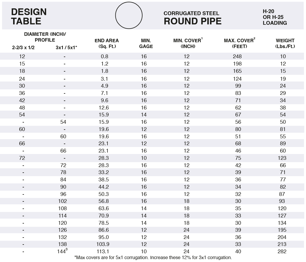
1. Minimum cover is measured from top of pipe to top of subgrade or top of rigid pavement. Minimum cover for heavy construction equipment or other excessive loading is 48 inches. H-20 or H-25 live loads are assumed in all cases.
2. Maximum height of cover is based on minimum gages shown. Thicker gauges, where available, can accept greater heights of cover and extend service life. Contact Pacific Corrugated Pipe Company for complete tables for all corrugated pipe products with available gages and corresponding height of cover tables.
3. 144 inch and larger diameters exceed the flexibility factor (ff=.033) allowable in AASHTO Bridge Specifications (Section 12) for 3″x1″ or 5″x1″ corrugation pipe in embankment type installations. Flexibility factor can be increased to ff=.060 in accordance with ASTM Specification A 796 for trench type installations. Contact Pacific Corrugated Pipe Company for information on recommended backfill materials and procedures for installing large diameter corrugated metal pipe.
NOTE: Pipe-arch dimensions shown are nominal and should not be used to design headwall structures or for other uses where dimensions are critical. Actual dimensions will be “plus” in the rise dimension and “minus” in the span dimension. Contact your Pacific Corrugated sales engineer for manufacturing tolerances and layout details for pipe-arches, and for complete height of cover tables for all other corrugated pipe products.
The information in this brochure should be checked in detail by the professional engineer responsible for the project design to verify its accuracy; also, the assumptions and methods used to obtain the information should be reviewed to make certain they are applicable and suitable for the design.
Tables adapted from AISI Handbook of Steel Drainage and Construction Products.
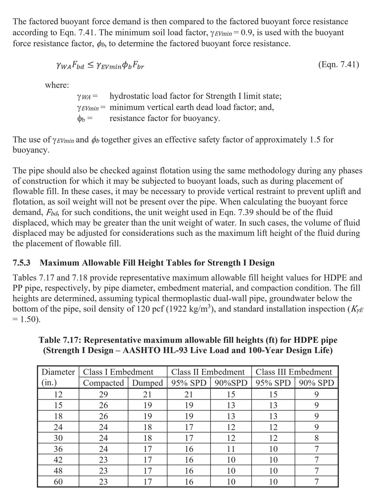
Corrugated Plastic Pipe Fill Height Chart